

Solar PV System Design Guide: String Sizing, Tilt Optimization & Energy Yield Simulation
Proper PV system design is critical for maximizing energy yield, ensuring equipment longevity, and meeting financial return targets. This technical guide covers the key design considerations for utility-scale and commercial solar installations.String Sizing FundamentalsMaximum string voltage: Calculate Voc at minimum site temperature using temperature coefficient (e.g., -0.27%/°C for TOPCon). Must not exceed inverter maximum DC input voltage (typically 1500V).Minimum string voltage: Calculate Vmpp at maximum site temperature. Must remain above inverter MPPT lower limit for full power harvest.Formula: Voc(Tmin) = Voc(STC) × [1 + TkVoc × (Tmin - 25)], where TkVoc is temperature coefficient of VocString length: Typically 26-32 modules per string for 1500V system with 700W bifacial modulesTilt Angle OptimizationLatitudeFixed Tilt (Optimal)Single-Axis Tracker Gain0-15° (Equatorial)10-15°+15-20%15-30° (Subtropical)20-25°+20-28%30-45° (Temperate)25-35°+25-35%45-60° (Northern)35-50°+15-25%Energy Yield SimulationSoftware tools: PVsyst (industry standard), SAM (NREL, free), Helioscope (cloud-based rapid design)Weather data: Use TMY (Typical Meteorological Year) from Meteonorm, SolarGIS, or NASA POWERLoss factors to model: soiling (2-5%), mismatch (1-2%), wiring (1.5%), inverter clipping (0-3%), degradation (0.4%/yr for TOPCon), transformer losses (1%), availability (1-2%)Bifacial modeling: Use view factor model or ray-tracing; ground albedo typically 0.20-0.25 (grass), 0.30-0.40 (sand/concrete)DC/AC Ratio SelectionTypical range: 1.20-1.40 for fixed-tilt, 1.15-1.30 for single-axis trackerHigher DC/AC ratio increases morning/evening energy capture but adds clipping losses at middayOptimal ratio depends on module cost, inverter cost, and PPA/tariff structureFor time-of-use tariffs valuing evening energy: pair with west-facing bifacial or storage
Battery Energy Storage Sizing Guide: C-Rate, Duration & Grid Service Requirements
Properly sizing a battery energy storage system (BESS) requires balancing technical requirements, grid service obligations, and financial optimization. This guide helps energy developers and system integrators select the right capacity, power, and duration for their specific application.Key Sizing ParametersEnergy capacity (MWh): Total stored energy — determines duration at rated powerPower rating (MW): Maximum charge/discharge rate — determines instantaneous grid service capabilityDuration (hours): Energy ÷ Power — typically 1-4 hours for grid-scale, 4-8+ for long-durationC-rate: Power/Energy ratio — 0.25C = 4-hour duration, 0.5C = 2-hour, 1C = 1-hourApplication-Based SizingApplicationDurationC-RateCycles/YearChemistryFrequency regulation0.5-1 hr1-2C3,000-5,000LFP / Na-ionPeak shaving2-4 hr0.25-0.5C300-500LFPSolar time-shift2-4 hr0.25-0.5C350-450LFPCapacity firming4-6 hr0.17-0.25C250-365LFPBackup / resilience4-8 hr0.125-0.25C50-100LFPLong-duration8-100 hr50-200Iron-air / flowDegradation & OverbuildLFP degrades approximately 2-3% per year at 1 cycle/day — plan for 20% capacity overbuild to meet end-of-life (EOL) contractual requirementsAugmentation strategy: install additional battery racks at years 8-10 to restore capacityWarranty typically guarantees 80% SOH at 15 years for LFP at specified cycling regimeFinancial OptimizationRevenue stacking: Combine multiple grid services (frequency regulation + peak shaving + capacity) to maximize returnsLCOS calculation: Include CAPEX, O&M, augmentation, degradation, and residual valueTypical LCOS: $0.05-0.08/kWh for 4-hour LFP system at current pricingIRR targets: 8-12% unlevered for merchant storage, 6-8% for contracted capacity
Our Address
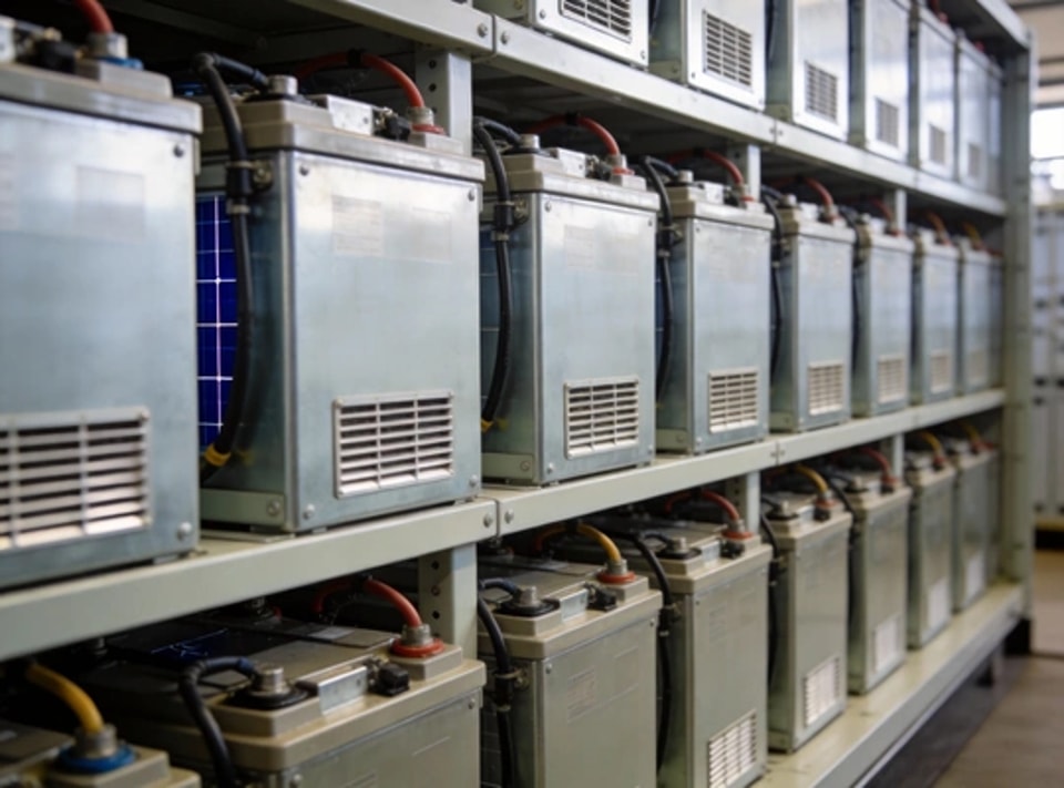
Product Gallery


项目.jpg")